Introduction to PlantUML
PlantUML is a versatile tool that allows users to create UML diagrams from plain text descriptions. This capability makes it accessible to both novice and experienced users, as it simplifies the process of diagram creation. 1
The primary purpose of PlantUML is to help users visualize systems and document software architecture. By converting textual descriptions into graphical representations, it aids in understanding complex systems and facilitates communication among team members. 2
One of the key benefits of PlantUML is its concise and efficient syntax. This allows users to quickly create and update diagrams without the need for extensive graphical manipulation, making it a time-saving tool for software development and documentation. 3
PlantUML can be seamlessly integrated into various Integrated Development Environments (IDEs) such as IntelliJ IDEA and Visual Studio Code. This integration enhances the user experience by allowing developers to create and manage diagrams within their preferred coding environment. 4
The versatility of PlantUML is evident in its support for multiple types of UML diagrams, including class, sequence, use case, and component diagrams. This wide range of supported diagrams makes it a comprehensive tool for documenting different aspects of software systems. 5
connect2grp.medium.com
Basic Syntax for Class Diagrams
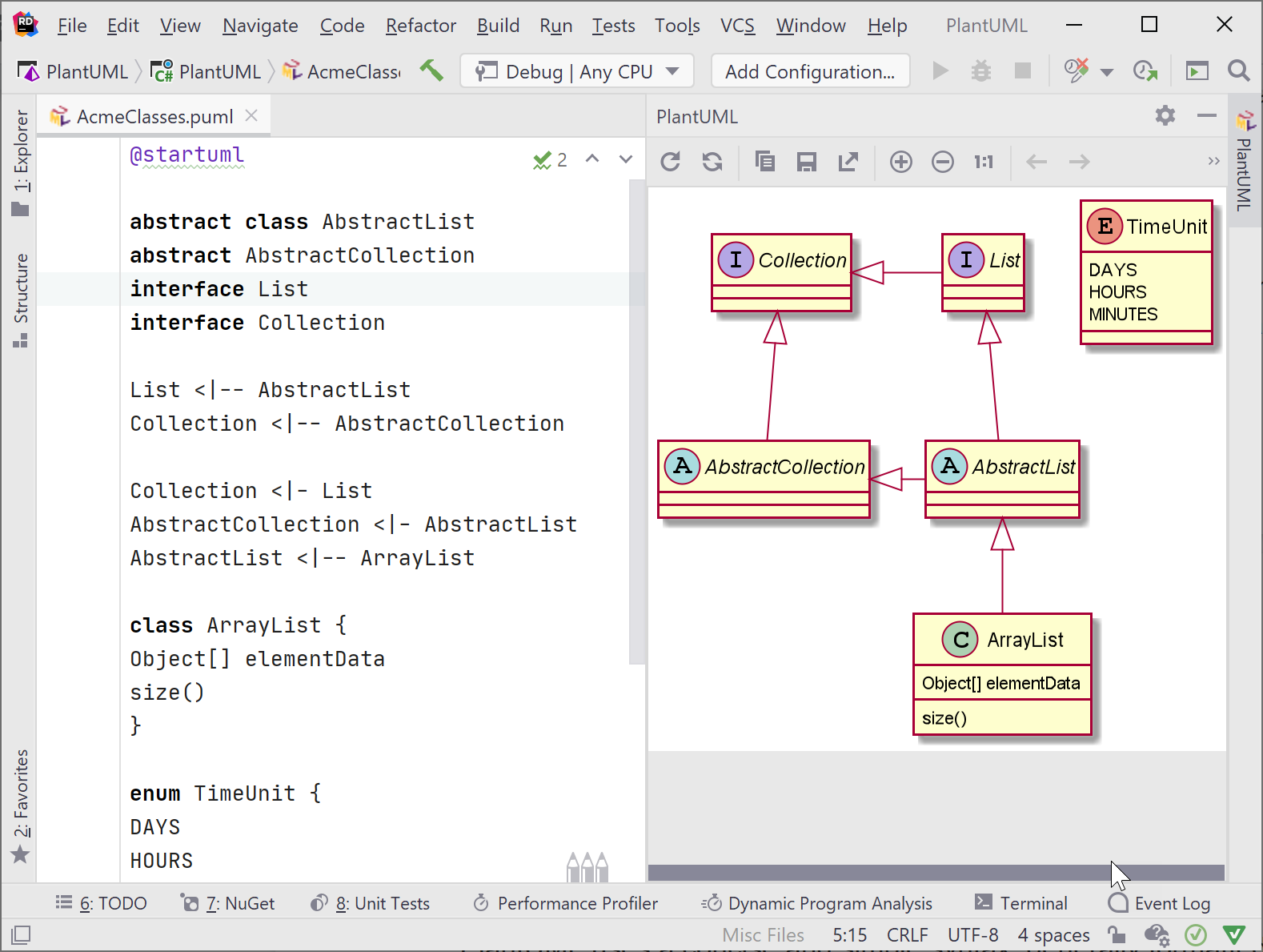
To define a class in PlantUML, you start with the keyword ‘class’ followed by the class name. This mirrors the syntax used in many object-oriented programming languages, making it intuitive for developers. 5
attributes within a class are defined using the format ‘attributeName: dataType’. This clear and concise syntax allows for easy representation of class properties, ensuring that the diagram accurately reflects the structure of the class. 3
methods are defined using the format ‘methodName()’. This notation is straightforward and aligns with common programming practices, making it easy to understand and implement. 3
Every PlantUML file must begin with the ‘@startuml’ marker and end with the ‘@enduml’ marker. These markers delineate the start and end of the UML diagram, ensuring that the syntax is correctly interpreted by the PlantUML tool. 3
For example, the syntax ‘class User { name: String; age: int; getName() }’ creates a class named ‘User’ with two attributes, ‘name’ and ‘age’, and a method ‘getName’. This example demonstrates how to encapsulate class properties and behaviors succinctly. 3
Advanced Syntax and Features
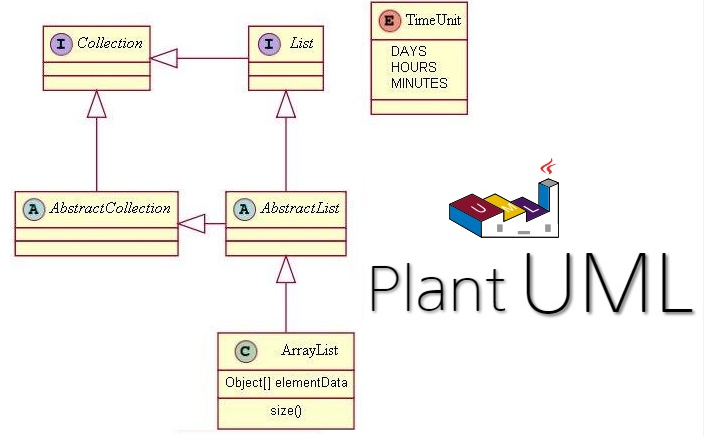
inheritance in PlantUML is represented using the ‘<|–‘ symbol. This notation is used to show that one class inherits from another, establishing a parent-child relationship. This is particularly useful in object-oriented design to depict class hierarchies and shared behaviors. 5
Interfaces in PlantUML are defined using the ‘interface‘ keyword followed by the interface name. This allows for the representation of abstract types that define a set of methods without implementing them, ensuring that any class implementing the interface adheres to the specified contract. 3
relationships between classes in PlantUML can be depicted using various symbols. For instance, ‘–‘ denotes an association, ‘*–‘ represents a composition, and ‘o–‘ indicates an aggregation. These symbols help in illustrating how classes interact and depend on each other within the system. 5
Abstract classes in PlantUML are defined using the ‘abstract class‘ keyword. Abstract classes cannot be instantiated and are meant to be subclassed. They often contain abstract methods that must be implemented by subclasses, providing a template for other classes to follow. 5
visibility of attributes and methods in PlantUML is indicated using specific symbols: ‘+’ for public, ‘-‘ for private, and ‘#’ for protected. These symbols help in defining the access level of class members, ensuring encapsulation and proper access control within the class structure. 5

Layout Control Techniques
direction commands in PlantUML, such as ‘left’, ‘right’, ‘up’, and ‘down’, are essential for controlling the direction of arrows. These commands help in defining the flow and relationships between different elements in a class diagram, ensuring clarity and readability. 6
Spacing between elements in a PlantUML diagram can be adjusted using the ‘NodeSep’ command. This command allows for fine-tuning the distance between nodes, which can be crucial for maintaining a clean and organized layout, especially in complex diagrams. 7
invisible edges, created using the ‘style=invis’ command, are a powerful tool for arranging nodes without displaying the connecting lines. This technique can be used to influence the layout subtly, ensuring that nodes are positioned in a desired manner without cluttering the diagram with unnecessary edges. 8
The ‘rankdir=LR’ command is used to arrange elements from left to right in a PlantUML diagram. This command is particularly useful for creating horizontal layouts, which can be more intuitive and easier to read, especially when dealing with a sequence of related elements. 8
Fine-tuning the layout of a PlantUML diagram should be approached with caution. While adjustments can improve readability, excessive fine-tuning can lead to unstable layouts. It’s important to strike a balance between manual adjustments and allowing the layout engine to optimize the diagram automatically. 8
Examples of Class Diagrams
A simple example of a class diagram in PlantUML might include a few classes such as ‘User’, ‘Account’, and ‘Transaction’. These classes can be connected with basic relationships like inheritance and association, providing a clear and concise visual representation of their interactions. 5
For a more complex example, consider a diagram that includes multiple classes, interfaces, and relationships. This might involve abstract classes, multiple inheritance, and various types of associations, offering a detailed view of the system’s architecture and the interactions between its components. 3
A use case example could document a user management system. This diagram would include classes like ‘User’, ‘Admin’, ‘Role’, and ‘Permission’, showing how users interact with the system, the roles they can assume, and the permissions associated with each role. 9
Component interaction diagrams illustrate how different components of a system interact with each other. For instance, a diagram might show how a ‘User Interface’ component communicates with a ‘Backend Service’ and a ‘Database’, highlighting the flow of data and control between these components. 6
A real-world example might involve a sample diagram from a project, such as an e-commerce platform. This diagram could include classes like ‘Product’, ‘Order’, ‘Customer’, and ‘Payment’, demonstrating practical usage and providing insights into the system’s design and functionality. 10
Common Issues and Troubleshooting
Syntax errors in PlantUML diagrams often stem from incorrect placement of ‘@startuml’ and ‘@enduml’ markers. Ensuring these markers are correctly placed at the beginning and end of your PlantUML code is crucial for proper diagram rendering. Misplacement can lead to errors and incomplete diagrams. 11
Unrecognized commands can be a result of an improperly installed or outdated PlantUML plugin. Verifying the installation and ensuring the plugin is up-to-date can resolve many issues. This step is essential for the correct interpretation of PlantUML syntax and commands. 11
Layout problems in PlantUML can be mitigated by using direction commands and invisible edges. Commands like ‘left’, ‘right’, ‘up’, and ‘down’ can help control the placement of elements. Invisible edges can also be used to fine-tune the layout, although this requires careful handling to avoid instability in the diagram. 8
PlantUML may change the order of fields in a class diagram, which can be controlled using layout hints. By specifying the order and direction of links, you can influence the arrangement of fields and classes, ensuring a more logical and readable diagram. 7
For complex diagrams, it is advisable to split them into smaller, more manageable parts. This approach not only simplifies the diagram but also enhances readability and comprehension. Breaking down complex structures into simpler sub-diagrams can make the overall system easier to understand and maintain. 12
Best Practices for Creating Diagrams
Organizing elements logically within a diagram is crucial for enhancing readability. By arranging related components together and ensuring a clear flow of information, users can quickly grasp the structure and relationships within the diagram. This practice minimizes confusion and makes the diagram more intuitive. 13
Consistency in naming conventions and styles is essential for maintaining clarity and uniformity across diagrams. Using the same naming patterns and visual styles helps users to easily identify and understand different elements, reducing the cognitive load required to interpret the diagram. 14
Including comments and metadata in your diagrams provides valuable context and version information. This practice ensures that anyone viewing the diagram can understand its purpose, authorship, and any relevant updates, fostering better communication and collaboration among team members. 14
To avoid overly complex diagrams, it is advisable to split them into smaller, more manageable sections. This approach not only makes each section easier to understand but also allows for more focused analysis and troubleshooting of specific parts of the system. 8
Using version control systems is a best practice for tracking changes and collaborating on diagrams. Tools like Git enable teams to see the history of modifications, understand the rationale behind changes, and work together more effectively, ensuring that everyone is on the same page. 14
Resources and Further Reading
The PlantUML Official Documentation provides a comprehensive guide on the syntax and features of PlantUML. It covers various types of UML diagrams, including class diagrams, sequence diagrams, and use case diagrams, making it an essential resource for both beginners and advanced users. 5
The JetBrains Blog offers a detailed tutorial on creating UML diagrams using PlantUML in Rider. This tutorial is particularly useful for developers familiar with JetBrains IDEs, as it demonstrates how to integrate PlantUML seamlessly into their workflow, enhancing productivity and diagram accuracy. 3
The PlantUML Q&A Forum is a community-driven platform where users can ask questions and share solutions related to PlantUML. This forum is invaluable for troubleshooting specific issues, learning best practices, and discovering new ways to utilize PlantUML’s features effectively. 8
The GitHub Repository for PlantUML contains source code and examples of various PlantUML diagrams. It includes detailed documentation and sample files, making it a practical resource for developers looking to understand the implementation details and customize their diagrams. 15
Stack Overflow hosts numerous discussions and solutions for common PlantUML issues. Users can find answers to specific questions, such as how to change the direction of diagrams or organize elements, making it a go-to resource for quick problem-solving and learning from the community’s collective experience. 16

Whenn some one searches for his vital thing, so he/she
wants to be available that in detail, so that thing is maintained
over here.